Friday, January 28, 2011

Modifications V : Replacing more LEDs

I am not sure if i should bother you all with every LED i replace, but my first try went so well that i am happy to share my latest update too.

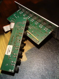
This time i very bravely went for two (2!) LEDs at once. The module i picked for this was the A-166 Dual Logic Module. I thought the 2 inverted trigger output LEDs at the bottom of the front-plate were perfect for this. I don't use these a lot, so the lower 2 LEDs are almost always burning, what also gives a nice effect in the dark.

To reach the soldering-points of the 2 LEDs i had to remove one of the modules boards on the backside.
This was was easy as each board is only fixed with its own 8 sockets. After that i removed the flat connector between the two boards and that created enough access to do my work.

De-soldering the old LEDs was a piece of cake, and the new ones fitted quite easy too.
See my earlier LED replacement post HERE for (safety) remarks, warnings and additional info.

Tuesday, January 25, 2011

SiteTip III : Tim Stinchcombe's A-100/Modular Webpage

Another useful resource for A-100 and other DIY-projects is Tim Stinchcomb's personal A-100/Modular webpage.

Very interesting for starting DIY-ers, this site is a very interesting read. Don't let the design of the pages mislead you ;)

Most of the projects and instructions on this site can be found via the Doepfer Yahoo Usergroup, but this is a neat collection of some of the A-100 modifications that are not too difficult.

You can also find some Plan B modification instructions on this site, together with other nice DIY-projects like for example this cool stereo LED VU-meter built in a blind-panel to fit a Eurorack system.

Great site... very inspiring.

Sunday, January 23, 2011

To Patch... or Not to Patch

'patch'  -  [ pach ] :

verb: To connect together, as the inputs and outputs of various modules, generally with patch-cords.

noun: The configuration of hookups and settings that result from the process of patching, and, by extension, the sound that such a configuration creates.

from: Vintage Synthesizers by Mark Vail

- Related forms:
patch·a·ble, adjective
patcher, noun
patchless, adjective
un·patched, adjective
well-patched, adjective

Thursday, January 20, 2011

Modifications IV : Replacing LEDs

 Instead of going the easy route by ordering A-100 modules with blue LEDs, i just had to try to do this by myself. Lately you can pre-order modules with blue LEDs installed for a 2 Euro fee per assembled LED, but i don't believe that was possible when i bought my first modules.

It wasn't a very difficult job, perhaps more difficult was choosing which LED i wanted to replace. As always, i try to keep the look of the system as logic as possible, other examples are the colored switches and colored patch-cables.
( also see Color-Coding )
Plus, for my first replacement i wanted to find an LED that was a easily accessible. I found out that the Doepfer boards are so full that many of the LED are in tight spots on the boards.

I'm glad that i had finally found one; the overload LED from my A-119 External Input / Envelope Follower.
Removing the old LED was easy. I bent it out of it's front-plate hole and heated the soldering-points one by one while pulling the LED out softly.
After that i took the new blue LED, bent the 90 degrees angle the same way as the old one and pushed it gently into the A-100's board again. The solder that was left from the old LED was enough to tightly fix the new one.

A few notes:
- You can not use any LED, only use the same ones that Doepfer provides. Always check documentation for more info.
- Due to technical reasons not every red LED can be replaced by a blue one. ( like the Vactrol modules ) Check each module's webpage before you start.
- Don't forget to check the polarity of the LED's ( + / - )
- Blue LED's are actually transparent/white when they are not lit.

Monday, January 17, 2011

Quick Tip IV : Ribbon Cable

A small personal advice for owners of an A-198 Ribbon Controller or R2M manual controller;

Please unplug the USB-cable when you are not using the instrument.
The weight of the cable has more then once broken the USB-connector on my Ribbon Controller.

Or try to keep the controller and cable on a flat surface...

...also see THIS post.

Friday, January 14, 2011

Blind Panels II

Beside for safety uses, as mentioned in one of my earlier posts, the blind-panels that Doepfer sells are also perfectly usable for all types of DIY-projects.
The 'standard' panels of 4,8,42 and 84 HP can be used for all types of original self-made modules or expanders. Sadly they don't have other sizes, but wouldn't it be nice if they had a 16HP and perhaps a 24HP to 'fill in the gaps'.

Drilling the metal plates is quite easy ( if you use the right tools ), and the panels come with pre-drilled mounting-holes.
If you don't like drilling, you can also order some pre-manufactured panels from the Doepfer A-100 specials list;


They still have many punched A-100 standard front panels of 4HP width, punched for 8 sockets, identical to A-180 front panel but without printing, very useful  for DIY or A-101-9 expansion  applications. You can save yourself some money by making your own A-180 multiple for almost half the price. (sockets can also be ordered at Doepfer )

Punched A-100 standard front panels of 8HP width are still available too. Punched for 5 potentiometers and 5 sockets (same as A-102, A-103, A-105, A-120, A-122, A-123, A-124, A-130, A-131, A-138), without silk screen printing.
They even  fit the Synovatron DIY1 and DIY2 kits. (*confirmed / ,but see feedback for remarks and more info)
Update March 3 2011: Synovatron now sells his own generic front panels for his DIY kits.

Doepfer also still has a few 14 HP front panels punched for 2 wheels and 4 sockets ( like A-174-2 ), without printing, that might useful e.g. for a DIY wheel module. Order it with two modulation wheels and you even get the front-plate for free...
Tuesday, January 11, 2011

Sunday, January 09, 2011

A-178 Theremin Control Voltage Source

The Theremin, invented in the late 1920's by Léon Theremin was one of the earliest electronic instruments.
The instrument is known for it's distinctive ( spooky ) sound, but most of all for it's playing method; Instead of playing it with a keyboard, the Theremin has antennas that sense the movement of the players hand, without touching the instrument.
Best known for playing the Theremin is Clara Rockmore, one of Theremins finest students.

Most theremins use two antennas, usually one for pitch and one for volume, so with two Doepfer A-178 Theremin Voltage Source modules, an oscillator (VCO) and an amplifier (VCA) module, it is quite easy to re-create the sound of a 'real' Theremin. You can even easily extend that sound by patching in filters or other modules.

And again, that is what makes the A-100 modular so versatile. 
Instead of just recreating the original Theremin you can use the module as a control voltage source for other modules. 

The voltages can be used for controlling any voltage controlled parameter of the A-100, e.g. pitch or pulsewidth (VCO A-110/111), loudness (VCA A-130/131/132), panning (A-134), filter frequency or resonance from all of the filter modules, phasing (A-125), frequency shift (A-126), resonance peaks (A-127), envelope parameters (A-141/142), and tempo (A-147), to name just a few ;-)

The Gate-output with adjustable threshold (not available on the original Theremin) is a nice extra output. I often use this for (re-) triggering notes or filter effects, but it can also be used for starting sequences (A-155) or for reset or switching functions (A-152).

Doepfer recommends if two or more A-178 are used the distance between the modules/antennas should be at least 30 cm to avoid interference.

Monday, January 03, 2011

Booktip V - The A-Z of Analogue Synthesizers by Peter Forrest


This 'Encyclopaedia of all the great analogue synthesizers and keyboards' is written by Peter Forrest and is probably one of the most detailed analog synthesizers-catalogs out there.

The books list all analog synthesizers that were ever produced, and is spread across 2 parts with a total of 600 pages, filled with useful info about manufacturers, statistics and lots of pictures in black and white.
Both books also have a 16-page full-color-section, stuffed with cool pictures.

The first edition of Part One (A-M) was published in 1994, two years before Part Two (N-Z) arrived. The Revised version of Part One was published in 1998.
Although the layout of the books and some b/w pictures may look a bit cheap the books are highly informative if you are interested in analogue synthesizer history.

ISBN Part One A-M revised 0 9524377 2 4
ISBN Part Two N-Z              0 9524377 1 6
Susurreal Publishing: http://www.vemia.co.uk/susurreal/